Civil3D : FEMA Floodplain and EPA Watershed Dynamo Scripts

 Civil3D : FEMA Floodplain and EPA Watershed Dynamo Scripts

Written by Andy Carter,PE | December 29, 2020


Download the Script

Download the Civil3D Dynamo scripts from my GitHub repository. 

https://github.com/andycarter-pe/Civil3D_WebService_Dynamo/archive/main.zip


Video Walkthrough (3 minutes)


Web Services for Drainage

There are several federal web services that are currently providing geospatial data that is essential for your design projects.  As a civil engineer that specializes in hydrologic and hydraulic design, I need to know the watershed delineation for the site  as well as the limits of the FEMA regulated floodplains.

For watershed delineations, the EPA WATER's service (Watershed Assessment, Tracking & Environmental Results System) provides for the request and delivery of pre-calculated watersheds and stream centerlines for the continental United States.


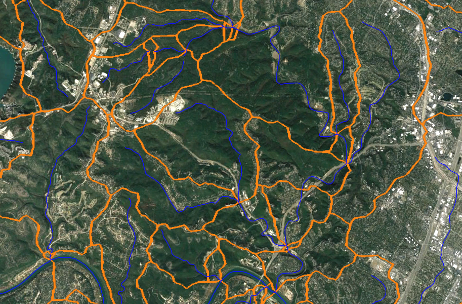
When you need FEMA floodplain limits on and adjacent to your subject site, most folks these days use FEMA's National Flood Hazard Layer (NFHL).  Typically, this is ingested through an image overlay map service that is used in either Google Earth, ArcGIS Pro or QGIS.


Dynamo: Getting AutoCAD Linework

I have created a couple of Dynamo scripts that makes a web request to these federal servers to get the needed AutoCAD linework for your drawing.  Here is a rough breakdown of what is going on:

  1.  User sets up a Civil3D drawing in the desired Coordinate Reference System (CRS)
  2.  User draws and selects ACAD item for spatial input
  3.  Dynamo converts items coordinates to Latitude/Longitude
  4.  Dynamo builds a URL to request the data from the REST endpoint as JSON
    1. Example  https://hazards.fema.gov/gis/nfhl/rest/services/public/NFHL/MapServer/27/query?&geometry=-97.786,30.352,-97.782,30.356&f=pjson
    2. Example  https://ofmpub.epa.gov/waters10/NavigationDelineation.Service?pNavigationType=UT&pStartComid=5781811&pOutputFlag=BOTH&pAggregationFlag=TRUE
  5.  JSON data is parsed with Dynamo to get linework
  6.  Lat/Long coordinates converted to local CRS 
  7.  Linework drawn inside AutoCAD / Civil3D

Stop (Collaborate and Listen)!

Prior to even thinking about using this script, you will need to install the Civil3DToolkit package for Dynamo.  This package is provided by Autodesk and provides functionality necessary for my scripts to work.


Download the Script

Download the Civil3D Dynamo scripts from my GitHub repository. 

https://github.com/andycarter-pe/Civil3D_WebService_Dynamo/archive/main.zip


Some Warnings

The scripts are "as is" and are provided without warranty of any kind.  You can modify any script but, if you do, know that you are required to provide me proper credit.

Please comment below if you have questions or issues.  While I can't provide support, I would like to know what issues y'all are seeing.


Civil3D : Dynamo Script for Pipe Crossings

 Civil3D : Dynamo Script for Pipe Crossings

Written by Andy Carter,PE | November 6, 2020


Pipe Crossing and Clearance

When using pipe networks in Civil3D, the civil designer is always required to determine if (1) pipes are not clashing with each other and (2) if the pipes have the appropriate [and often statutory] minimum vertical clearance.  In municipalities that I have designed projects, this minimum vertical clearance between the outside diameters of the pipes is 2 feet (24 inches).

So....

You have designed all of your pipe networks both horizontally and vertically.   Some of these are gravity networks (storm drain, waste water) and some of these networks are pressure (water, force mains).

Using Dynamo for Civil3D, I am providing you a FREE tool to evaluate all the pipe crossings provide the minimum vertical clearance.


Stop (Collaborate and Listen)!

Prior to even thinking about using this script, you will need to install the Civil3DToolkit package for Dyanmo.  This package is provided by Autodesk and provides functionality necessary for my script to work.


Download the Script

Download the Civil3D Dynamo script from my GitHub repository. 

https://github.com/andycarter-pe/Civil3D_PipeConflict/archive/main.zip


Some Warnings

The script is "as is" and is provided without warranty of any kind.  You can modify the script but, if you do, know that you are required to provide me proper credit.

1) I have noted that some alignments may not be properly processed.  If that is a problem, place all alignments on the same layer or move the alignments to a '0' layer.

2) DO NOT run the script in 'Automatic' mode.  The creation of a new pipe in automatic mode will likely crash Civil3D.

3) Set the Layer color to "ByLayer" prior to running.

Please comment below if you have questions or issues.  While I can't provide support, I would like to know what issues y'all are seeing.


Video Walkthrough (2 minutes)


HEC-RAS : Bridge Models

  HEC-RAS : Bridge Modeling

Written by Andy Carter,PE | October 13, 2020


Know the Lingo

When it comes to bridge modeling in HEC-RAS, there are a few items that you need to take into consideration:

  • Station Control:  All bridges inside of HEC-RAS are a based upon a alignment layout.  Think of it like a cross section.  You have a horizontal alignment where a station (X value) has a corresponding elevation (Z value). 
  • Bounding Cross Sections:  Cross sections both upstream and downstream of the structure to be modeled are necessary.  To make modeling easier, it is recommended that both of these cross sections be the same length and therefore have the same station control.
  • High Chord:  The 'high chord' is the top of the bridge to be modeled.  For an existing bridge, often LiDAR is available to help model these station-elevation pairs, which is typically the roadway elevation, rail road or other similar item.  Sometimes the high chord should be modeled to include a concrete barrier, hand rail or metal beam guardrail.
  • Low Chord:  The 'low chord' is the bottom of the bridge.  These are station-elevation pairs modeled together with the high-chord.  Often the low chord represents the bottom of the girder section or the bottom of the I-beams.
  • Piers:  Between each bridge span a pier can be modeled.  These are entered along the station control at width-elevation pairs.  I typically model the piers at an elevation of zero and ending at an elevation between the high and low chord.  Often the bents capping the piers are wider than the piers and are modeled as part of the pier.
  • Abutments:  At the end of bridge span, bridges have abutments.  If this abutment is vertical it can be modeled with geometric points of the low chord.  It the abutment is sloping, it can be modeled in HEC-RAS with station elevation-pairs along the control alignment.  This is done to make sure that the conveyance (flow) area under the bridge is correctly modeled.
  • Ineffective Flow Areas  As water flows though a bridge, it accelerates and funnels into to area under the bridge.  As water flows out from under a bridge, the water spreads out and expands back into the full conveyance area of the floodplain.  While water moves quickly through the bridge opening, areas of the upstream and downstream bounding cross sections that are not adjacent to the bridge opening may be wet but have little to no velocity or conveyance.  Around a bridge, it is necessary to model ineffective flow areas so that HEC-RAS knows areas that are likely to get wet but have no velocity or flood conveyance.

A video tutorial

Wow! It seems like there are several items to manage when modeling a bridge.  How to keep all of them straight?  I have added a video that walks through the whole bridge modeling process.  Enjoy.


Video Walkthrough (27 minutes)